The device may only be opened by specialized personnel.
The device must be connected to a socket with earth contact.
Ensure easy access to the power outlets.
Caution, risk of electric shock: To disconnect the power supply, all power sources must be disconnected to avoid the risk of electric shock.

Caution, risk of electric shock

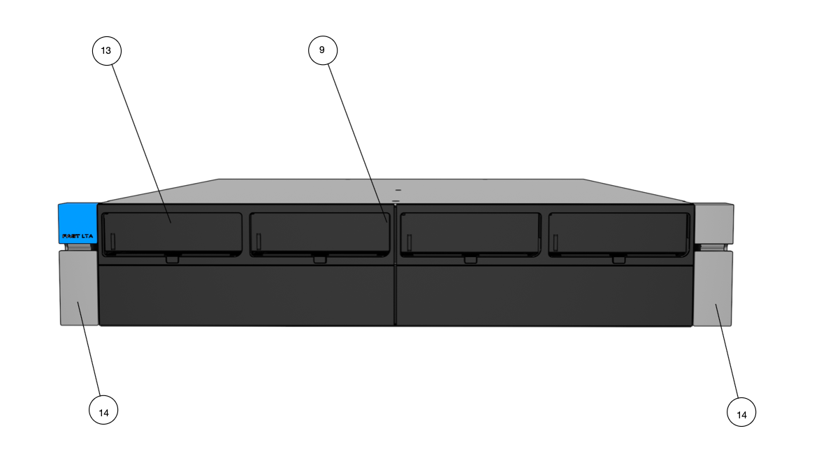
The Silent Brick Controller X-Series is the base unit. The controller includes the control unit for the Silent Brick System, up to 8 slots (13) for Silent Brick Pro storage containers, as well as two power supplies (16) for energy supply.
At the lower corners of the front side of the device, there are the locking levers (14). With these levers, the anchoring between the device and the rack rails can be released.
|
No. |
Designation |
|
9 |
Operating state display Silent Brick Slot |
|
13 |
Slots for Silent Bricks |
|
14 |
Locking Lever |
|
No. |
Designation |
|
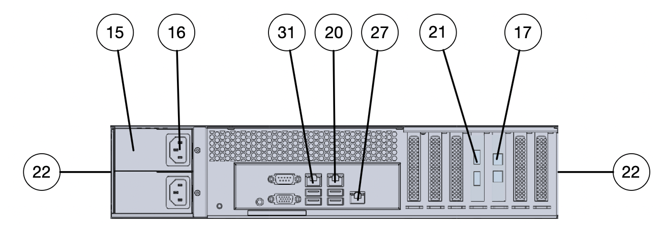
16 |
Power Supply |
|
17 |
SAS connectors for connecting expansions (SFF-8644) |
|
20 |
Management connection (1Gbit Ethernet RJ45) |
|
21 |
Data connections depending on equipment variant |
|
22 |
Rack rails |
|
27 |
IPMI connection (1GB Ethernet RJ45, independent web interface for hardware monitoring) |
|
28 |
Fan |
|
29 |
Power |
|
31 |
Last Resort Interface |