Configure Network
In the 'Network' section, you can view and configure the network settings.
Set Network Identification
-
➤ To set the network identification, proceed as follows:
-
➤ Click the 'Edit' button in the 'Network Identification' section.
-
➤ The 'Network Identification' window will open.
-
➤ Enter a host name.
-
➤ Enter a domain name valid for both IPv4 and IPv6.
-
➤ Optionally, enter a domain name valid only for IPv6.
-
➤ To confirm your entries, click the “Save” button.
-
➤ To cancel the operation, click the “Cancel” button.
Configure SSL Certificate
The 'SSL-Certificate' button allows uploading a custom SSL certificate for the Silent Brick System's web interface.
The certificate, the private key, and the corresponding CA are required for this.
|
WARNING |
The certificate used must be created without a passphrase. |
-
➤ To configure an SSL certificate, proceed as follows:
-
➤ Click the “Edit” button in the “SSL-Certificate” section.
-
➤ Upload the certificate, the key, and the corresponding CA in the subsequent window.
-
➤ Use the upper area to select pre-existing text files containing the certificates.
-
➤ Use the lower area to paste the certificates as text.
-
-
➤ Save the changes by clicking the "Save" button.
Configure the Management Network
-
➤ To configure the management network, proceed as follows:
-
➤ Select the “management” option in the “NIC” section.
-
➤ Click the “Edit” button.
-
➤ The “NIC - management” window will be displayed.
Set Automatically
-
➤ Check the “Use DHCP” option.
-
➤ To confirm your entry, click the “Save” button.
-
➤ To cancel the operation, click the “Cancel” button.
Set Manually
Ensure that the checkmark for the “Use DHCP” option for the Data Network has already been removed and saved.
-
➤ Remove the checkmark from the “Use DHCP” option, if necessary.
-
➤ Enter a default gateway, if necessary.
-
➤ Enter up to two DNS servers, if necessary.
-
➤ Enter an IP(v4) address.
-
➤ Enter a network mask.
-
➤ Set the "Bonding Mode" to the desired configuration. Default: "Active-backup".
-
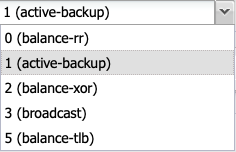
➤ 0: This mode transmits packets sequentially, distributed from the first to the last interface. This mode provides load balancing as well as fault tolerance.
-
➤ 1: This mode places a physical interface into a backup state, which is only activated when the physical link on the active interface fails. Within a bond, only one interface is active at any time. This mode provides fault tolerance.
-
➤ 2: Transmission in this mode is based on an XOR formula, ensuring that the same interface is consistently used for a given destination. This mode provides load balancing as well as fault tolerance.
-
➤ 3: Broadcast mode transmits all data on all interfaces. This mode is reserved for special use cases and provides fault tolerance.
-
➤ 4: The 802.3ad mode is known as Dynamic Link Aggregation mode. It creates an aggregation of network cards with identical speed and duplex settings. This mode requires a switch that supports IEEE 802.3ad Dynamic Link Aggregation.
-
➤ 5: This mode is called Adaptive Load Balancing. Outgoing traffic is distributed according to the utilization of the network interfaces.
-
➤ To confirm your entry, click the “Save” button.
-
➤ To cancel your input, click the 'Cancel' button.
To configure TCP/IP(v6), proceed as follows:
-
➤ Enter an IP address for the router.
-
➤ Enter an IP(v6) address.
-
➤ To confirm your entries, click the “Save” button.
-
➤ To cancel your entries, click the “Cancel” button.
Configure Data Network
To configure the Data Network, proceed as follows:
-
➤ Select the 'data' option in the 'NIC' section.
-
➤ Click the “Edit” button.
-
➤ The window „NIC - data” is displayed.
Set Automatically
-
➤ Check the “Use DHCP” option.
-
➤ To confirm your entry, click the “Save” button.
-
➤ To cancel your input, click the 'Cancel' button.
Set Manually
Please ensure that the checkbox for the option "Use DHCP" on the Management Interface has been unchecked.
-
➤ Remove the checkmark from the “Use DHCP” option, if necessary.
-
➤ Enter a Default Gateway if necessary. Warning: This setting overrides the configuration on the Management Network.
-
➤ Enter up to two DNS servers if necessary. Warning: This setting overrides the configuration on the Management Network.
-
➤ Enter an IP(v4) address.
-
➤ Enter a network mask.
-
➤ Uncheck "Link Autonegotiation" if you need to adjust the connection settings.
-
➤ Check "Jumbo Frames" to enable Jumbo Frames if required.
-
➤ Set the "Bonding Mode" to the desired configuration. Default: "Active-backup".
-
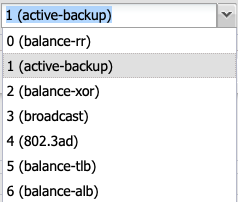
➤ 0: This mode transmits packets sequentially, distributed from the first to the last interface. This mode provides load balancing as well as fault tolerance.
-
➤ 1: This mode places a physical interface into a backup state, which is only activated when the physical link on the active interface fails. Within a bond, only one interface is active at any time. This mode provides fault tolerance.
-
➤ 2: Transmission in this mode is based on an XOR formula, ensuring that the same interface is consistently used for a given destination. This mode provides load balancing as well as fault tolerance.
-
➤ 3: Broadcast mode transmits all data on all interfaces. This mode is reserved for special use cases and provides fault tolerance.
-
➤ 4: The 802.3ad mode is known as Dynamic Link Aggregation mode. It creates an aggregation of network cards with identical speed and duplex settings. This mode requires a switch that supports IEEE 802.3ad Dynamic Link Aggregation.
-
➤ 5: This mode is called Adaptive Load Balancing. Outgoing traffic is distributed according to the utilization of the network interfaces.
-
➤ 6: Adaptive load balancing distributes packets based on interface utilization for both sending and receiving. It also considers the speeds of the connections. Data are transmitted sequentially over all connections. All connections must be on the same switch.
-
➤ To save your inputs, click the “Save” button.
-
➤ To cancel your entries, click the “Cancel” button.
To configure TCP/IP (v6), proceed as follows:
-
➤ Enter a router.
-
➤ Enter an IP(v6) address.
-
➤ To confirm your entries, click the “Save” button.
-
➤ To cancel your entries, click the “Cancel” button.
Merging Data and Management Networks
By default, since software version 2.45, the data and management networks have been merged. This prevents complex routing and ensures system accessibility.
When merging the data and management networks after a network separation, the IP address previously assigned to the management network is transferred to the data network interface.
To merge the data and management networks, proceed as follows:
-
➤ Assign the desired IP address to the management network.
-
➤ (see “Configure Management Network”)
-
➤ Click the “Combine Data & Management” button.
-
➤ The desired IP address is now available on the Data Port.
Separate Data and Management Networks
If the Data and Management networks have previously been merged, they can also be separated again.
When separating, the IP address is assigned to the Management Interface.
Proceed as follows:
-
➤ Click the “Separate Data & Management” button.
-
➤ The shared IP address is now available on the Management Port.
Check the Status of Network Ports

The user interface provides indicators to verify the network connection by displaying the status of the network ports.
Depending on the configuration and system, a distinction is made between the Management Port (Mgmt) and the Data Port (Data).
Please refer to the wiring diagrams of the respective devices for the correct port numbering.
|
Color |
Status |
|---|---|
|
Green |
Connected |
|
Red |
Not connected |
|
Gray |
Unknown |
|
Yellow |
Error |
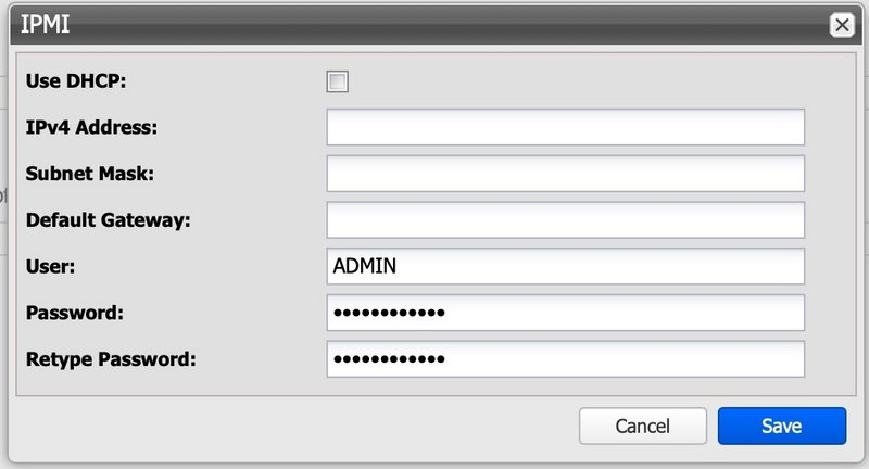
Configure IPMI interface (Silent Brick Controller only)
The IPMI interface is used for maintenance access to the server portion of the Silent Brick Controller, providing support personnel with KVM access for advanced fault analysis. The IP address can be configured via DHCP or by assigning a static IP address.
Configure routing
To configure routing, proceed as follows:
-
➤ Click the 'Edit' button in the 'Routing' section.
-
➤ The 'Routing' window will appear.
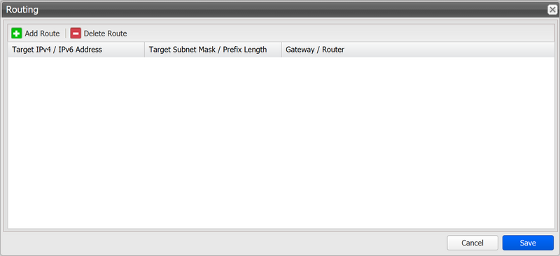
To add a route, proceed as follows:
-
➤ Click the “Add Route” button.
-
➤ The “Add Route” window will appear.
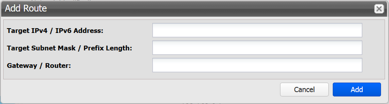
-
➤ Enter an IP(v4)/IP(v6) address.
-
➤ Enter a network mask or prefix length.
-
➤ Enter a gateway.
-
➤ To confirm your entries, click the “Add” button.
-
➤ To cancel your entries, click the “Cancel” button.
To remove a route, proceed as follows:
-
➤ Click a route to select it.
-
➤ Click the “Delete Route” button.